CAD Keyring - Week 1
Fusion 360 is a cloud-based 3D modelling, CAD, CAM, and PCB software platform for product design and manufacturing. I have some experience using Fusion360 to create some computer-aided design during the ICPD module last semester. I learnt how to use the various tools and constraints in Fusion360. This tutorial will act as a refresher to help me refresh the skills I learnt last semester on creating CAD using Fusion 360. We are tasked to create a keyring design of our name on Fusion360.
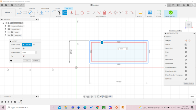
Firstly, i created a sketch and selected the 'TOP' plane. I then drew a 2-point rectangle with dimensions of 65mm by 25mm.

I used the 'Offset tool' to offset the sketch by 2mm inside the rectangle. I keyed the offset position to be '-2mm' in order to create the offset of 2mm inside the sketch. This created a smaller rectangle inside the rectangle I drew.
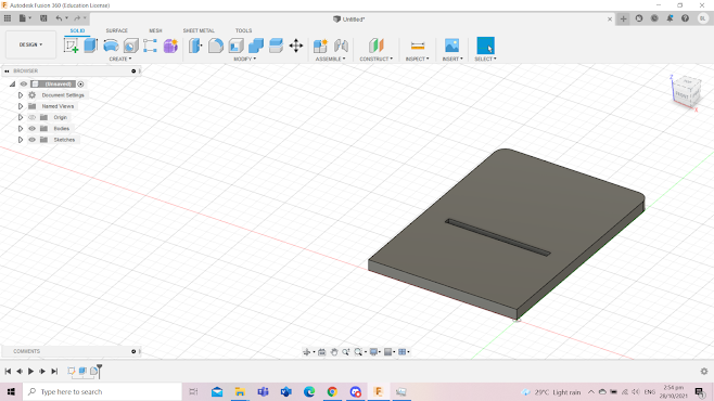
Next, I used the fillet tool to round the four edges of the sketch. This does not only make the design of the keyring more aesthetic but it also makes it safer for users by removing the sharp edges which may cause the users to cut themselves. I used a fillet radius of 5mm.


Next, I drew a point in the middle of the line and created a circle of a radius of 5mm on the point. I selected the text option and added my name to the keyring. I adjusted the height of the text to 10mm to fit the sketch and alighted it onto the middle.

Now, its time to changed the sketch from 2D to 3D. I clicked 'finish sketch' and selected the outer base and the text and extruded them by 3mm. I then selected the inner base and extruded it by 1.5mm. This will make the text and the outer base pop out slightly more than the inner base so that the text will be visible on the keyring. I did not extrude the hole thus the hole will remain on the keyring. Finally, i clicked 'hide sketch' to show the final product.

CAD Handphone Stand - Week 2
Today, I am tasked with creating a CAD of a handphone stand using parametric design. Parametric modelling is an approach to 3D CAD in which you capture design intent using features and constraints, and this allows users to automate repetitive changes, such as those found in families of product parts.
The best-voted design will be laser cut during the holidays. I have an idea in mind and have done a rough sketch of the design with all of the dimensions. I would also need to consider laser kerfing in the calculation of the dimensions of my handphone stand as the CAD is used for laser cutting. I plan to create two separate pieces which will be joined together. The first piece will be the base where the handphone rest on and the second will be the stand that supports the handphone stand. The base will contain a hole where the stand is inserted through to join the 2 parts.
How I created the Handphone Stand
First, I will need to define the parameters. I click change parameters and set parameters for the length, width, thickness, length of the hole, the width of the hole, length of the stand and width of the stand. I will need to decrease the length and width of the hole by 2mm and increase the length and width of the stand by 2mm to compensate for laser kerf during laser cutting. The thickness of the material will be 5mm as we are using plywood.

I drew a rectangle with the length and width parameters. This will be the base the handphone rest on.

Next, to create the sketch for the hole, I drew 2 horizontal and 2 vertical lines to create a rectangle inside the sketch. I used the sketch dimension tool to set the length and the width of the rectangle to be the hole length and hole width.

I used the trim tool to remove the excess lines.

Next, I used the extrude tool to extrude the sketch by the thickness parameter. I also fillet the 2 top corners by 5mm.
Now, for the stand. I start off by drawing a rectangle with the length of the "stand length" parameter and the width of the "stand width" parameter. This part will be the part that will be inserted through the hole and will be what keeps the stand upright.

Next, I used a combination of the offset tool, line tool and trim tool to create the part where the bottom of the handphone will rest on. Firstly I offset the sketch my 9mm to match the width of first part of the construction.


Reflection:
I found this activity to be really fun and interesting. I feel that creating a CAD of a handphone stand on my own was not easy as I needed to think of a design that was doable with my limited skills on Fusion360. Since this CAD is for laser cutting, I would need to consider laser kerfing in calculation the dimensions of my structure. This activity made me use many of the skills I learnt on Fusion360 from last semesters such as extrusion and offsetting. I believe this activity made me more familiar with Fusion360 as while making the handphone stand if I had an idea in mind, it was intuitive to use a certain tool instead of having to think of what tool I should use like before. I also learn the use of parameters and how much it makes drawing CADs easier. I believe that using parametric will greatly benefit me in future projects in CCPD as not only will I be able to complete the more complicated CAD design presented to me but I will also be able to complete it within a shorter amount of time. This is because parametric designs allow us to automate repetitive changes, such as those found in a group of product parts.
I used to think that parametric design in CAD would be complicated and time-consuming, however, how that I learn that if I have done the proper planning of the structure and dimensions of the CAD, I could use parametric design to create my CAD more efficiently. In the future, I would incorporate parametric designs into my CAD.
No comments:
Post a Comment