Monday, 13 December 2021

3D Printing

 3D Printing

Today, I am going to draw an object which cannot be made subtractively on Fusion360 and then 3D print the object that I have created. I have decided that I will create a door hinge. The hinge will consist of 3 parts. 2 "Leaf" and a pin. A hinge is an object that cannot be made subtractively as it consists of 3 different parts with detailed structures, Furthermore, the dimensions of each part must be precise in order for each part to fit into one another. The leaves also contain narrow holes which will be difficult to be made subtractively. 

Anatomy of a door hinge (Home Stratosphere, 2018).

The pin will be inserted through the hole of the two leaves which will act as the pivot for the leaves to rotate. I will be excluding the screw holes in my design to simplify the 3D printing process.

Designing Object on Fusion360


Firstly, I will create the leaf. I start off by creating a rectangle with dimensions of 40mm by 2.5mm. At one point in the rectangle, I drew a 2-point circle with an outer diameter of 10mm and an inner diameter of 4mm. This will be the side view of the hinge. I specified the outer diameter parameter to be 10mm and the inner diameter parameter to be 4mm to save some time later. This is the side view of one of the leaves.


Next, I extruded the rectangle by 60mm and the circle by 20mm. I did not extrude the inner circle.


Next, I use the rectangular pattern feature to add another cylinder with the hole to the other side of the hinge. The spacing between the 2 cylinders is 20mm. Since this is my first time using this feature, it took some troubleshooting before I could get it to do what I wanted. This is one of the parts of the hinge.


Now, I shall create the other leaf of the hinge. Firstly, I hid the first component that I create and extruded the previous sketch by 60mm. I "Showed" the first component and extruded spacing in between the cylinders to create another cylinder.


Lastly, I created the pin which will be inserted into the holes which will act as the pivot of the hinge,
I created a new component and extruded the circle in the sketch by 60mm. I also added an offset of 1mm on both sides so the pin will stick out of the frame by a little.


Here are all three parts assembled together to create the door hinge!


Here is the link for the .f3d and stl files for the object I designed: https://drive.google.com/drive/folders/1mRfDA-3c7ju904KbsvfBgln-wZVfdRGm?usp=sharing

3D printing Cura Settings

These are the Cura settings I used for the 3D printing. 

Cura Settings


I used the default settings found under the "Standard Quality" profile and modified it slightly. I increased the printing speed from 50.0mm/s to 75.0 mm/s so that the 3D printing process will take a shorter amount of time. I also had to add support as my structure contained an overhang.

Images of 3D Printed Object

Object with Support Intact

Object without Support

Hero Shot with Object

Reflection
For the object design on Fusion360 activity, it was fairly simple as the previous CPDD sessions have provided me with the necessary knowledge and skills needed to complete this task. It was a fun activity as I was able to use the skills that I learnt to complete the task on my own. It was also very satisfying to be able to create an object with a more complicated design with little help as it really shows how much I have improved on my CAD skills. 

For the 3D printing activity, I was able to complete it without much trouble with the help of the friendly seniors that were also present at the lab. Since it was my first time using the Cura software and operating the 3D printer, they guide me through the settings on Cura and the procedures of operating the 3D printer. This activity is important as it has helped me familiarise myself with using the Cura software and the 3D printer. I found this activity really interesting as this is my first time seeing a 3D printer at work to bring the object I designed on Fusion360 to life. The movement of the 3D printer was very precise and how they were able to turn strings of PLA filament into an object really intrigued me. 

However, my object took a little over an hour to print which was much longer than expected. Furthermore, I had a difficult time removing the support from my object. If I were to do this activity again, I would increase the printing speed to reduce the time spend printing my object from 75mm/s to 100mm/s. I would also decrease the support density from the previous 20% to maybe around 15% to make the support easier to remove.

This activity will be extremely important to future projects in CPDD as we will be using 3D printers to print parts required for our chemical product, the soft boiled egg maker. Previously, I used to think that 3D printing is complicated and I won't be able to do it as there were a lot of settings with many different functions required when 3D printing and the procedures seemed difficult. However, now that I have understood what these settings do and how to operate the 3D printer, I am now much more confident in performing 3D printing. I hope to be able to hone my 3D printing skills especially selecting the optimal Cura settings for printing an object.

Reference
Home Stratosphere. (2018). Parts of a Door (Incl. Frame, Knob and Hinge Diagrams). [online] Available at: https://www.homestratosphere.com/door-parts/.

Wednesday, 24 November 2021

Arduino Programming

Arduino Programming

Today, we are tasked to complete activities on interfacing input and output devices.

These are the activities that we need to complete:

1. Input devices:

        a. Interface a Potentiometer Analog Input to maker UNO

            board and measure its signal in serial monitor Arduino IDE

        b. Interface an LDR to maker UNO board and measure its

            signal in serial monitor Arduino IDE

2. Output devices:

        a. Interface 3 LEDs (Red, Yellow, Green) to maker UNO

            board and program it to perform something (fade or flash

            etc)

        b. Interface the DC motor to maker UNO board and

             program it to on and off using push button on the board


Potentiometer Analog Input

TinkerCAD

As I rotate the knob on the potentiometer clockwise, the frequency of blinks on the LED bulb decreases. This is because the resistance of the potentiometer will increase as the knob is rotated. clockwise. A resister is needed when interfacing with an LED to prevent the LED from exploding. By adding "Serial.begin(9600);" under "voidsetup()" and "Serial.println(sensorValue);" under "voidloop()", we can monitor the sensor value in the serial monitor. In the serial monitor, the sensor value will change whenever the knob is rotated.


The serial monitor shows a increase in the sensor value as the knob on the potentiometer is turned clockwise, with the lowest point being a senservalue of 0 and the highest point having a sensorValue of 1023.

Code:
// C++ code
//
int sensorValue = 0;

void setup()
{
  pinMode(A0, INPUT);
  pinMode(LED_BUILTIN, OUTPUT);
}

void loop()
{
  // read the value from the sensor
  sensorValue = analogRead(A0);
  // turn the LED on
  digitalWrite(LED_BUILTIN, HIGH);
  // pause the program for <sensorValue> millseconds
  delay(sensorValue); // Wait for sensorValue millisecond(s)
  // turn the LED off
  digitalWrite(LED_BUILTIN, LOW);
  // pause the program for <sensorValue> millseconds
  delay(sensorValue); // Wait for sensorValue millisecond(s)
}


How The Code Works
void setup()
{
  pinMode(A0, INPUT);
  pinMode(13, OUTPUT);
}
Pin A0 is configured as an input and Pin 13 is configured as an output to control the LED.

void loop()
{
  // read the value from the sensor
  sensorValue = analogRead(A0);
Within the main loop, a function called "analogRead();" checks the state of pin A0  and stores that value in the variable "sensorValue".

 // turn the LED on
  digitalWrite(13, HIGH);
  // pause the program for <sensorValue> millseconds
  delay(sensorValue); // Wait for sensorValue millisecond(s)
  // turn the LED off
  digitalWrite(13, LOW);
  // pause the program for <sensorValue> millseconds
  delay(sensorValue); // Wait for sensorValue millisecond(s)
}
This string of code controls the flashing of the LED. The "digitalwrite" cause the LED to be "HIGH" or "LOW" which turns the LED on or off respectively. As the potentiometer is rotated and the sensor value changes, which will result in a corresponding change in the duration of each flash of the LED.


LDR

TinkerCAD

LED is dim when LDR is covered (low light intensity)

LED is bright when LDR is exposed to high light intensity

When the LDR detects a high light intensity, the LDR's resistance will decrease causing the LED to be brighter. When the LDR detects a low light intensity, the LDR's resistance will increase causing the LED to be dimmer. The LDR is interfaced with the LED in series.


Code:

// C++ code
//
int sensorVal = 0;

void setup()
{
  pinMode(13, OUTPUT);
}

void loop()
{
  digitalWrite(13, HIGH);
  delay(1000); // Wait for 1000 millisecond(s)
  digitalWrite(13, LOW);
  delay(1000); // Wait for 1000 millisecond(s)
}

How The Code Works

int sensorVal = 0;

void setup()
{
  pinMode(13, OUTPUT);
}

"int sensorVal = 0;" creates a variable for the sensor. Under void setup, we declare PIN 13 as the output.

void loop()
{
  digitalWrite(13, HIGH);
  delay(1000); // Wait for 1000 millisecond(s)
  digitalWrite(13, LOW);
  delay(1000); // Wait for 1000 millisecond(s)
}

When PIN 13 is HIGH, LED will turn on, When PIN 13 is LOW, LED will turn off. There is a 1000ms delay between each action

Flashing LED

TinkerCAD


The 3 LEDs are consecutively light up for 1 second in a sequence with a 1 second pause in between. This is similar to what we did in the competency test during our Arduino practical. I used PINs 12, 10 and 8 as the output. The red LED is connected to PIN 12, green LED is connected to PIN 10 and the yellow LED is connected to PIN 8.


Code:

// C++ code
//
int i = 0;

void setup()
{
  pinMode(12, OUTPUT);
  pinMode(10, OUTPUT);
  pinMode(8, OUTPUT);
}

void loop()
{
  digitalWrite(12, HIGH);
  delay(1000); // Wait for 1000 millisecond(s)
  digitalWrite(12, LOW);
  delay(1000); // Wait for 1000 millisecond(s)
  digitalWrite(10, HIGH);
  delay(1000); // Wait for 1000 millisecond(s)
  digitalWrite(10, LOW);
  delay(1000); // Wait for 1000 millisecond(s)
  digitalWrite(8, HIGH);
  delay(1000); // Wait for 1000 millisecond(s)
  digitalWrite(8, LOW);
  delay(1000); // Wait for 1000 millisecond(s)
}

How The Code Works

int i = 0;

void setup()
{
  pinMode(12, OUTPUT);
  pinMode(10, OUTPUT);
  pinMode(8, OUTPUT);
}

Under void setup, we declare PINs 12, 10, 8, as the output.

void loop()
{
  digitalWrite(12, HIGH);
  delay(1000); // Wait for 1000 millisecond(s)
  digitalWrite(12, LOW);
  delay(1000); // Wait for 1000 millisecond(s)
  digitalWrite(10, HIGH);
  delay(1000); // Wait for 1000 millisecond(s)
  digitalWrite(10, LOW);
  delay(1000); // Wait for 1000 millisecond(s)
  digitalWrite(8, HIGH);
  delay(1000); // Wait for 1000 millisecond(s)
  digitalWrite(8, LOW);
  delay(1000); // Wait for 1000 millisecond(s)
}

This string of code causes the LED to flash in sequence consecutively. The "digitalwrite" cause the LED to be "HIGH" or "LOW" which turns the LED on or off respectively. The PIN 12 output is set to HIGH which causes an LED to light up. The LED lights up for 1 second as the delay is 1000ms. The PIN 12 output is then set to LOW for 1 second which causes the LED on pin 12 to turn off for 1 second. The same thing repeats for the LED connected to PIN 10 and 8 in sequence. Since the code is in a voidloop, it will repeat infinitely.


DC Motor

TinkerCAD


When the button is pushed, the DC motor will turn on. The DC motor is turned off when the button is pushed once more. Initially, when interfacing the DC motor, I had trouble getting it to work. After some inspection and research, I realised that I have interfaced the transistor in the opposite direction. I was previously not aware that the transistor had different pins, the emitter (e), base(b) and collector(c) pins. After interfacing the transistor in the correct direction, the DC motor finally turned on. I also had to interface on the Arduino Uno board slightly different as I would on TinkerCAD as on TinkerCAD we had to add in a button whereas the Arduino Uno board already has a build-in button.
 
Code:
int buttonState = 0;
int status = true;

void setup(){
  pinMode(2, INPUT_PULLUP);
  pinMode(13, OUTPUT);
}

void loop()
{
  // read the state of the pushbutton value
  buttonState = digitalRead(2);
  // check if pushbutton is pressed.  if it is, the
  // buttonState is HIGH
  if (digitalRead(2) == true) 
  {
    status = !status;
    digitalWrite(13, status);
  }
  while(digitalRead(2) == true);
  delay(50);
}

How The Code Works

int buttonState = 0;
int status = true;

void setup(){
  pinMode(2, INPUT_PULLUP);
  pinMode(13, OUTPUT);
}
Within the void setup, PIN 2 is declared as the input and enable the internal pull up resistor. So, by default, PIN2 status will always be HIGH. PIN 13 is declared as the output.
void loop()
{
  // read the state of the pushbutton value
  buttonState = digitalRead(2);
  // check if pushbutton is pressed.  if it is, the
  // buttonState is HIGH
  if (digitalRead(2) == true) 
  {
    status = !status;
    digitalWrite(13, status);
  }
  while(digitalRead(2) == true);
  delay(50);
}
Within the void loop, "buttonState = digitalRead(2);" check if pushbutton is pressed.  if it is, the buttonState is HIGH and the output PIN 13 will be HIGH, causing the DC motor to turn on. When the button is pressed again, the buttonState will be LOW and the DC motor will turn off.


Reflection
For the activities, I had to interface some input and output devices on TinkerCAD and use the breadboard and Arduino UNO board. Since this was my first time using TinkerCAD, I was initially unfamiliar with using it. But with the help of the videos provided, I quickly got accustomed to using it. I also had to program Arduino code to be uploaded to the Arduino board to complete each task. I used certain codes which were publicly available online and modified them to suit my objective. Interfacing the input and output devices were quite challenging for me and required many trial and error for it to work. I believe that what I learnt from doing these activities is important as my group plan to use Arduino programming and interfacing in our chemical product. Learning how to interface input and output devices on an Arduino board as most of the Arduino project will likely include both input and output devices.

Initially, I used to think that Arduino interfacing was very complicated and difficult to learn. However, how that I learnt the function and how to interface each component, I feel more confident in interfacing devices on the Arduino.  I hope to be able to create far more complicated projects with the use of Arduino in the future, either for the CP5070 module or for personal interest.

Wednesday, 3 November 2021

Laser Cutting

 Laser Cutting Practical

In this practical, we learnt how to perform laser cutting on either the FusionM2 or Fusion PRO laser cutter. We had to create a Standard Operating Procedure (SOP) for operating the laser cutter which was later improved upon after completing the practical. This is the improved version of the SOP.


Starting Up Operation

  1. Turn on the air compressor (not required for Fusion PRO)
  2. Turn on the fume extractor
  3. Turn on laser cutter machine
  4. Turn on the computer and pc.
Cordeldraw Operation
  1. Open CorelDraw on computer
  2. On the top left side of the screen, click the 'file' icon and import design file.
  3. Use the select tool and click on the part you would like to vector cut.
  4. Click the brush icon on the bottom right of the screen 

  5. Set stroke to 'hairline' and colour to red. (input colour components as R:255, G:0, B:0) Red is for vector cutting while green is for engraving.


  6. Use the select tool and click on the part you would like to engrave. Select brush icon (Stroke) and set the stroke to none. Select bucket icon (fill) and set the colour to green (input colour component components as R:0, G:255, B:0) 
  7. Click print icon at the top to send file to Epilog Dashboard

Epilog Dashboard Operation
  1. Turn on autofocus 
  2. Click on the folder icon to import material and change material thickness. Set power to 30%  for engraving. Check with personnel in charge if uncertain. (For both machines, position the object to cut at the top left corner so that the laser need not move too far to start cutting)
  3. Press print button


Laser Cutter Operation
  1. Check screen to see whether the filename is correct
  2. Open the lid of the laser cutter and place material inside laser cutter.
  3. Switch mode to jog more and use the joystick to position the laser to where you want to start laser cutting

  4. Press GO/START button to start cutting.
  5. Once laser cutting has been completed, wait 60 seconds before removing product from laser cutter to. This is to let the fumes be removed and let the material cool down.
Shut Down Operation
  1. Clear materials from laser cutter.
  2. Close lid of laser cutter.
  3. Switch off computer.
  4. Switch off laser cutter.
  5. Switch off Fume extractor
  6. Switch off air compressor
  7. Perform housekeeping


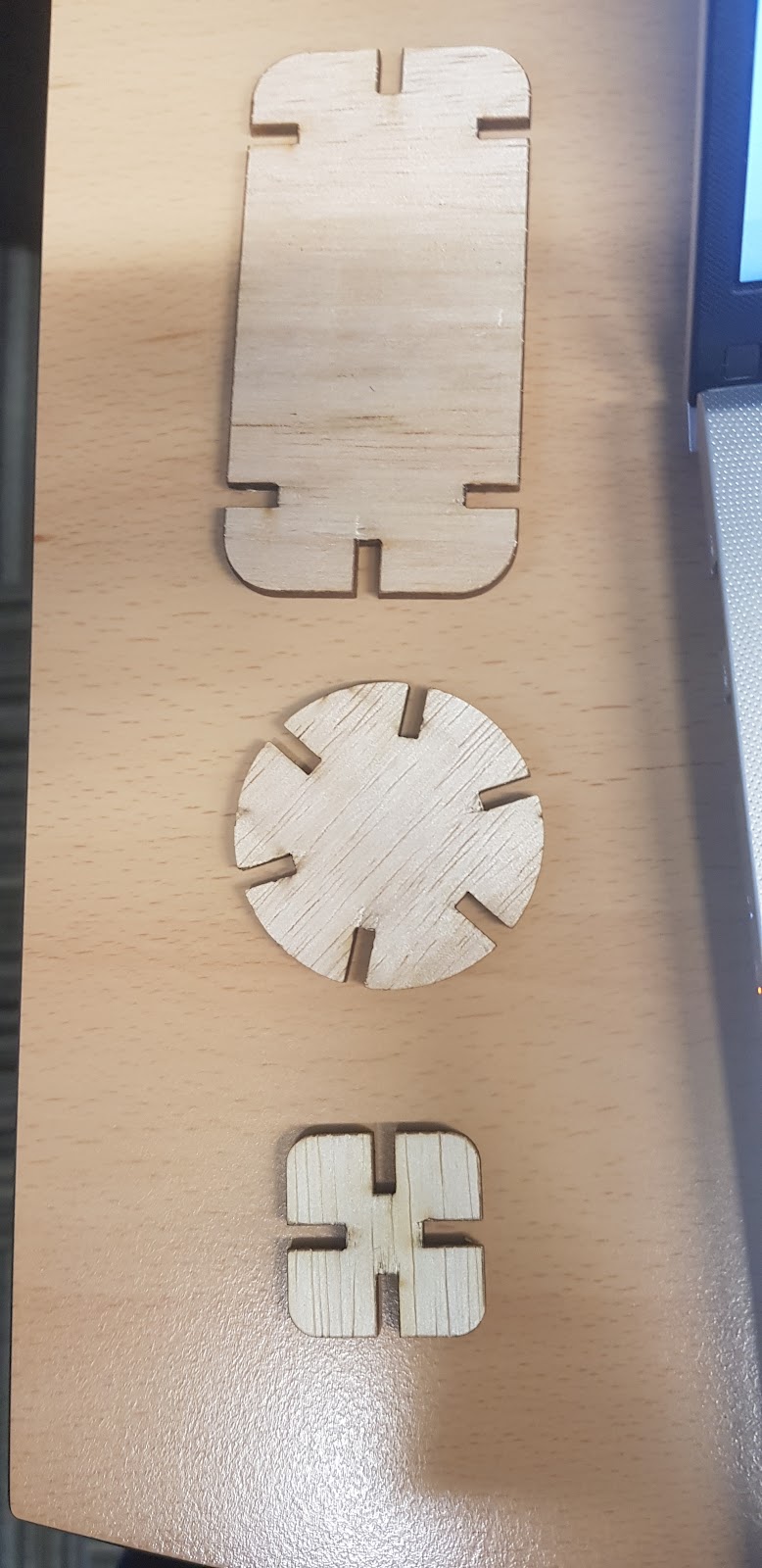
Theses are the pieces we printed!!


Reflection

During this practical, we learnt how to perform laser cutting with either the Fusion Pro or Fusion M2. We were first tested on the competency assessment and we realised that our SOP was not detailed, but thanks to the demonstrations from Mr Chan and supervisors, we were able to operate the machine. Next, when we were going to do all the pieces, we realised that all the pieces were not a perfect fit as we underestimated the kerf length, so we went back and redrew all the pieces on Fusion360. Unfortunately, we had to postpone the cutting due to some technical difficulties with our laptops. When we returned back to FabLab the following week, the wood we used was of a different thickness from what we had the previous week. We then change the parametric measures to change all respective gaps. Within a few minutes, we were able to change all 3 designs to their respective dimensions. We also had to decrease the gap more to take kerf into account. In the end, with the wood thickness of 4mm, we changed the size of the gap from the original 4.5mm to 3.5mm. The pieces fit perfectly into each other. 

I found today's practical really interesting as I got to see the laser cutter at work. The precision levels and edge quality achieved with laser cutting machines are better than traditional cutting methods. Furthermore, the process of using the laser cutting machine was straightforward and easy to use. I believe that what we learnt in this practical will benefit us in the future project in this module. The chemical product that we are planning to construct will be using parts that require laser cutting. 

Initially, we thought that adding parameters was just an extra redundant step, but after needing to make quick changes to the slot width, we realised that it was extremely useful and that it should be incorporated into all of our future designs using auto fusion360 especially for CADs with many repeating components. Instead of redesigning all the 3 pieces which will take around 20 mins, we just had to change the parameters for all the designs which took 4 times faster. As we were doing this, we were appreciative of and realized the importance of this function. Furthermore, we had firsthand experience with the importance of kerfs since our first attempt did not stick together, as did all the other groups. After reviewing other groups' attempts, we discussed and decided on a gap length that will work. As a result, our second attempt resulted in a perfect fit.

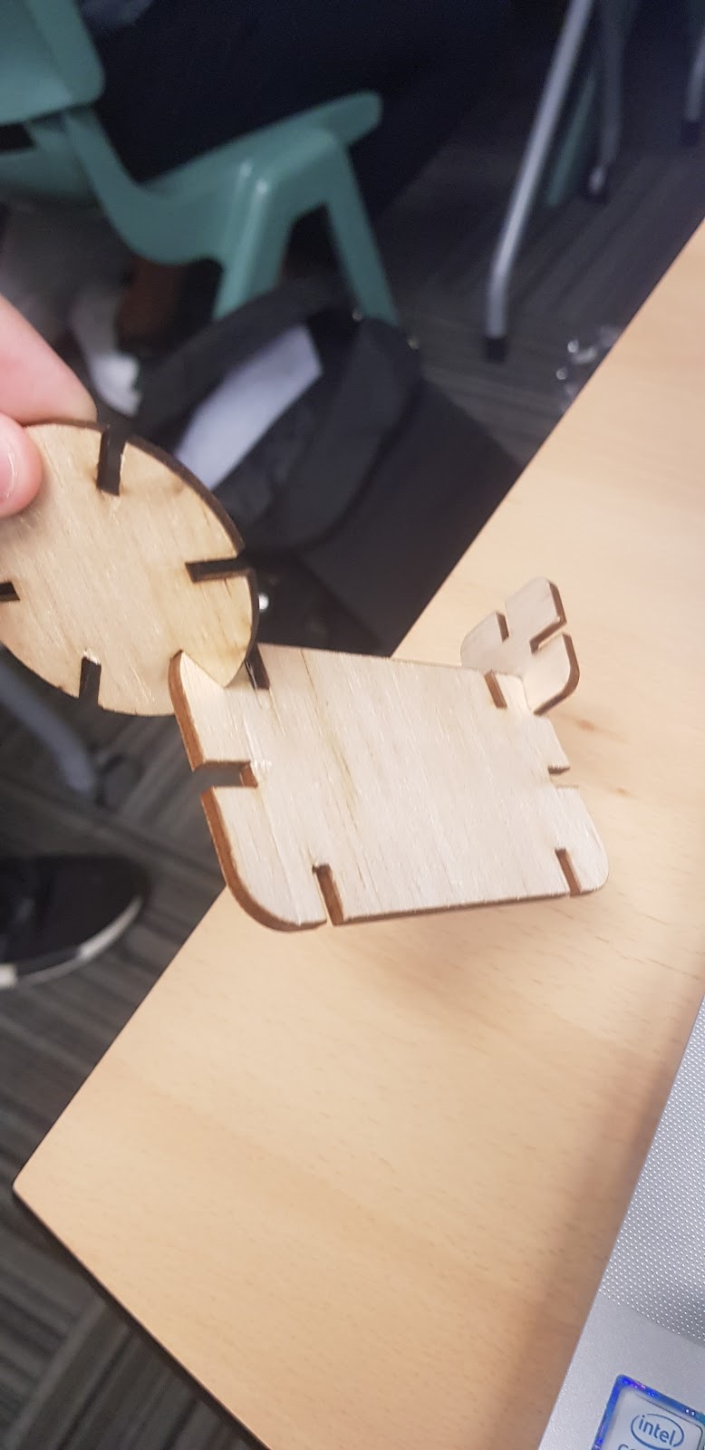
With the pieces we made using the laser cutter, we constructed a simple yet effective IPad stand.

Tuesday, 19 October 2021

CAD

CAD Keyring - Week 1

Fusion 360 is a cloud-based 3D modelling, CAD, CAM, and PCB software platform for product design and manufacturing. I have some experience using Fusion360 to create some computer-aided design during the ICPD module last semester. I learnt how to use the various tools and constraints in Fusion360. This tutorial will act as a refresher to help me refresh the skills I learnt last semester on creating CAD using  Fusion 360. We are tasked to create a keyring design of our name on Fusion360. 


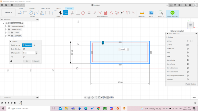
Firstly, i created a sketch and selected the 'TOP' plane. I then drew a 2-point rectangle with dimensions of 65mm by 25mm.


I used the 'Offset tool' to offset the sketch by 2mm inside the rectangle. I keyed the offset position to be '-2mm' in order to create the offset of 2mm inside the sketch. This created a smaller rectangle inside the rectangle I drew. 


Next, I used the fillet tool to round the four edges of the sketch. This does not only make the design of the keyring more aesthetic but it also makes it safer for users by removing the sharp edges which may cause the users to cut themselves. I used a fillet radius of 5mm.


Next up, I need to create some construction lines to use to align the hole in the keyring. I drew a line from the top of the sketch to the bottom, I then right-clicked the line and changed it into a construction line (as shown as a dotted line). This line is not used in the design of the sketch but only as a guide. I then selected the 'sketch dimension'  tool to position the construction line 7mm away from the left side of the rectangle.


Next, I drew a point in the middle of the line and created a circle of a radius of 5mm on the point. I selected the text option and added my name to the keyring. I adjusted the height of the text to 10mm to fit the sketch and alighted it onto the middle.


Now, its time to changed the sketch from 2D to 3D. I clicked 'finish sketch' and selected the outer base and the text and extruded them by 3mm. I then selected the inner base and extruded it by 1.5mm. This will make the text and the outer base pop out slightly more than the inner base so that the text will be visible on the keyring. I did not extrude the hole thus the hole will remain on the keyring. Finally, i clicked 'hide sketch' to show the final product.


So, here's the final product!


Conclusion:
This refresher has really cleared up some rust I had on creating CAD using Fusion360. In my opinion, Fusion360 is much easier to use compared to other CAD software I used in the past during Secondary School such as SOLIDWORKS. This is thanks to its layout which is simple to navigate around and its tools and features which makes it much easier to create complicated models. I believe that anyone will be able to learn CAD using Fusion360 and I hope to be able to hone my CAD skills using this software as I believe that CAD will be a crucial part of many jobs in the near future.


CAD Handphone Stand - Week 2


Today, I am tasked with creating a CAD of a handphone stand using parametric design. Parametric modelling is an approach to 3D CAD in which you capture design intent using features and constraints, and this allows users to automate repetitive changes, such as those found in families of product parts.

The best-voted design will be laser cut during the holidays. I have an idea in mind and have done a rough sketch of the design with all of the dimensions. I would also need to consider laser kerfing in the calculation of the dimensions of my handphone stand as the CAD is used for laser cutting. I plan to create two separate pieces which will be joined together. The first piece will be the base where the handphone rest on and the second will be the stand that supports the handphone stand. The base will contain a hole where the stand is inserted through to join the 2 parts. 


How I created the Handphone Stand

First, I will need to define the parameters. I click change parameters and set parameters for the length, width, thickness, length of the hole, the width of the hole, length of the stand and width of the stand. I will need to decrease the length and width of the hole by 2mm and increase the length and width of the stand by 2mm to compensate for laser kerf during laser cutting. The thickness of the material will be 5mm as we are using plywood.


I drew a rectangle with the length and width parameters. This will be the base the handphone rest on.


Next, to create the sketch for the hole, I drew 2 horizontal and 2 vertical lines to create a rectangle inside the sketch. I used the sketch dimension tool to set the length and the width of the rectangle to be the hole length and hole width.


I used the trim tool to remove the excess lines.


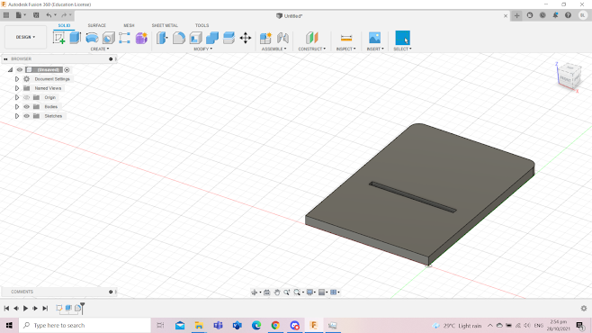
Next, I used the extrude tool to extrude the sketch by the thickness parameter. I also fillet the 2 top corners by 5mm.


Now, for the stand. I start off by drawing a rectangle with the length of the "stand length" parameter and the width of the "stand width" parameter. This part will be the part that will be inserted through the hole and will be what keeps the stand upright.


Next, I used a combination of the offset tool, line tool and trim tool to create the part where the bottom of the handphone will rest on. Firstly I offset the sketch my 9mm to match the width of first part of the construction. 


I then drew 2 lines to create a rectangle


I removed the excess lines. I also removed some excess material to make the handphone stand lighter and more portable.


Lastly, I extruded the stand by the thickness parameter. I also fillet the edges to make it look more appealing.


Here's the final product!


Reflection:

I found this activity to be really fun and interesting. I feel that creating a CAD of a handphone stand on my own was not easy as I needed to think of a design that was doable with my limited skills on Fusion360. Since this CAD is for laser cutting, I would need to consider laser kerfing in calculation the dimensions of my structure. This activity made me use many of the skills I learnt on Fusion360 from last semesters such as extrusion and offsetting. I believe this activity made me more familiar with Fusion360 as while making the handphone stand if I had an idea in mind, it was intuitive to use a certain tool instead of having to think of what tool I should use like before.  I also learn the use of parameters and how much it makes drawing CADs easier.  I believe that using parametric will greatly benefit me in future projects in CCPD as not only will I be able to complete the more complicated CAD design presented to me but I will also be able to complete it within a shorter amount of time. This is because parametric designs allow us to automate repetitive changes, such as those found in a group of product parts. 

I used to think that parametric design in CAD would be complicated and time-consuming, however, how that I learn that if I have done the proper planning of the structure and dimensions of the CAD, I could use parametric design to create my CAD more efficiently. In the future, I would incorporate parametric designs into my CAD.


Monday, 18 October 2021

Home

Hello, my name is Bjorn and I and the group leader of Group 3 which consist of Vernon as the timekeeper, Nigel as the treasurer and Roy as the discipline master. My role as the leader is to supervise our work, coordinate the group members and monitor our group progress.

Here are the ground rules that our team has discussed and unanimously agreed upon. 
  1. Do Your Part.
  2. Be Responsible for your Work.
  3. Be Punctual For Class and Team Meetings.
Firstly, everyone must do their part. This is important as it is not fair for a group member to be contributing less while getting the same grade as the others. We also agreed that we must be responsible for our work. When given a task, we should be responsible and put effort into our work. Lastly, we must be punctual for lessons and team meetings. This is so that each of the group members will not miss out on important parts of the lesson or team meeting.

We have also agreed that we would have a group call on WhatsApp or Discord to discuss any work or projects every Wednesday and Thursday at 6pm.

 By the end of this semester. I hope to be able to improve my leadership skills. Since the majority of this module consists of working as a group, I believe that this is the perfect opportunity to hone my skills as a leader. In order to achieve this, I will need to start taking the initiative. This includes starting discussions for ideas and taking the initiative to help my groupmates when in need.  By the end of this semester. I will know whether I have accomplished this goal because if my groupmates are able to rely on me. This will show that they will have trust in me as a leader to follow through and deliver on my promises. 

I would also like to improve my CAD skills on Fusion360. This is because I believe that CAD will be a crucial part of many jobs, especially in engineering. Not only can CAD be used in 3D printing, but it can also be used to create mechanical drawings for visualisation. I believe that I can hone my CAD skills in Fusion360 by experimenting with Fusion360 to create CADs on my own. I also plan to watch some Fusion360 tutorials on YouTube to gain a better understanding of all of the tools in Fusion360. By the end of this semester. I will know whether I have accomplished this goal because if I am able to create a more complex CAD without any assistance.